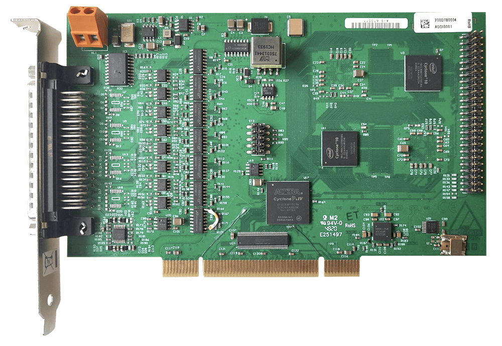
MSX-RDC-17 – Resolver-to-digital converter
The resolver-to-digital converter MSX-RDC-17 is a device for supplying and acquiring a resolver. It converts the position value given by the resolver into a digital incremental output signal. The resolution of the incremental encoder output can be defined using the switch on the front side of the MSX-RDC-17.
Get a quoteDescription
The MSX-RDC-17 is a device for supplying and acquiring a resolver. It converts the position value given by the resolver into a digital incremental output signal. The resolution of the incremental encoder output can be defined using the switch on the front side of the MSX-RDC-17.
Features
Power supply
- Nominal voltage: 5 V variant: +4.9 to +5.25 V, 135 mA @ 100 rps / 16-bit
- Overvoltage protection: 5 V variant: 5V TVS (Vbr 6.4-7 V, Vclamp 9.2 V, 400 W)
Resolver output/input
- Frequency: programmable 2 kHz to 20 kHz in 250 Hz steps
Incremental encoder output
- Output signals: incremental A+, A-, B+, B-, Index+, Index-
- Output type: differential, RS422
- Resolution: 10-/12-/14-/16-bit
Factory-configured by ADDI-DATA, not user-modifiable.
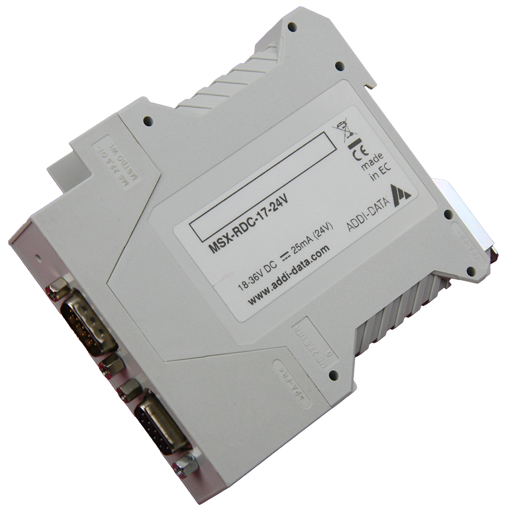
Power supply connector
For the power supply of the MSX-RDC-17, a 4-pin screw terminal is fixed on the bottom side of the housing. The Ground and the supply pins are connected internally with each other. For less current flow over the terminals, please connect all four pins externally with each other!
Resolver connector
The resolver has to be connected to the 9-pin D-Sub female connector on the front side of the MSX-RDC-17.
Reset button
On the front side of the MSX-RDC-17, a recessed reset button is provided. Pressing the button briefly performs a hardware reset of the device, reinitializing the resolver-to-digital converter and restoring normal operation. The button is intended for occasional use only, it does not need to be held and should not be actuated during normal operation.
Incremental encoder output
The incremental encoder signals are available at the 9-pin D-Sub male connector of the MSX-RDC-17.
Environmental conditions
- Operating temperature: 0-60°C (with forced ventilation)
- Storage temperature: -25°C to +70°C
- Relative air humidity at indoor installation: 50% at +40°C | 80% at +31°C
Index signal (incremental encoder output)
An Index pulse is generated when the absolute angular position passes through 0.
Intended use
The resolver-to-digital converter MSX-RDC-17 has to be used as electrical equipment for measurement, control and laboratory pursuant to the standard DIN EN IEC 61010-1. The power supply for the resolver-to-digital converter MSX-RDC-17 must fulfil the requirements of DIN EN IEC 62368-1 and DIN EN 55032 or IEC/CISPR 32 and DIN EN 55024 or IEC/CISPR 24.
Usage restrictions
The resolver-to-digital converter MSX-RDC-17 must not be used as a safety-related part (SRP).
The resolver-to-digital converter MSX-RDC-17 must not be used for safety-related functions, for example for emergency stop functions.
The resolver-to-digital converter MSX-RDC-17 must not be used in potentially explosive atmospheres.
The resolver-to-digital converter MSX-RDC-17 must not be used as electrical equipment according to the Low Voltage Directive 2014/35/EU.
Limits of use
All safety information and the instructions on this datasheet must be followed to ensure proper intended use. Uses of the resolver-to-digital converter beyond these specifications are considered as improper use. The manufacturer is not liable for damages resulting from improper use. The resolver-to-digital converter must remain in its anti-static packaging until it is installed. Please do not delete the identification numbers of the resolver-to-digital converter or the warranty claim will be invalid.
Additional information required
When placing your order, please provide us the following details:
- Response Frequency
- Resolution
- Amplitude reference signal
- Reference of the resolver